PICOSCOPE® 6000E SERIES
Ultra-deep-memory, high-performance oscilloscopes and MSOs3GHz 대역폭과 10GS/s 최대 샘플링 속도를 제공하는 4채널 PicoScope 6428E-D 제품도 출시되었습니다.
4개 또는 8개의 아날로그 채널이 있는 모델에는 타이밍 오류, 글리치, 드롭아웃, 누화 및 준안정성 문제와 같은 중요한 신호 무결성 문제를 드러내는 데 필요한 타이밍 및 진폭 분해능이 있습니다.
주요사양 :
일반적인 응용 분야
PicoScope 6000E 응용 프로그램 프로그래밍 인터페이스(API)는 고급 하드웨어 기능의 전체 집합에 대한 프로그래밍 액세스를 제공하며 다양한 사용자 지정 및 OEM 응용 프로그램을 개발하는 데 사용할 수 있습니다.
동급 최고의 대역폭, 샘플링 속도 및 메모리 깊이
(PicoScope 6428E-D의 경우 10GS/s)
5GS/s의 실시간 샘플링 속도로 보완된 최대 1GHz 아날로그 대역폭을 갖춘 PicoScope 6000E 시리즈 스코프는 200ps 시간 분해능으로 Single-shot Pulses를 표시할 수 있습니다.
10GS/s의 실시간 샘플링 속도로 보완된 최대 3GHz 아날로그 대역폭을 갖춘 PicoScope 6428E-D는 100ps 시간 분해능으로 Single-shot Pulses를 표시할 수 있습니다.
PicoScope 6000E 시리즈는 최대 4GS의 가장 깊은 캡처 메모리를 제공하며, 최대 샘플링 속도 5GS에서 200ms 파형을 캡처할 수 있습니다. PicoScope 6428E-D는 10GS/s에서 200ms 파형을 캡처할 수 있습니다.
PicoSDK를 사용하는 경우 스코프의 전체 메모리를 단일 파형에 할당하여 최대 5GS/s 샘플링 속도를 유지하여 최대 800ms의 놀라운 캡처 시간을 확보할 수 있습니다. SuperSpeed USB 3.0 인터페이스 및 하드웨어 Acceleration은 긴 캡처에서도 디스플레이가 매끄럽고 반응이 빠르도록 보장합니다. 6428E-D는 8비트 분해능에서 400ms 동안 최대 10GS/s 샘플링 속도를 유지할 수 있습니다.
PicoScope 6000E 시리즈는 오늘날의 고성능 임베디드 컴퓨터 및 차세대 임베디드 시스템 설계에 대한 엄격한 테스트를 수행하는데 필요한 파형 메모리, 분해능 및 분석 도구를 제공합니다.
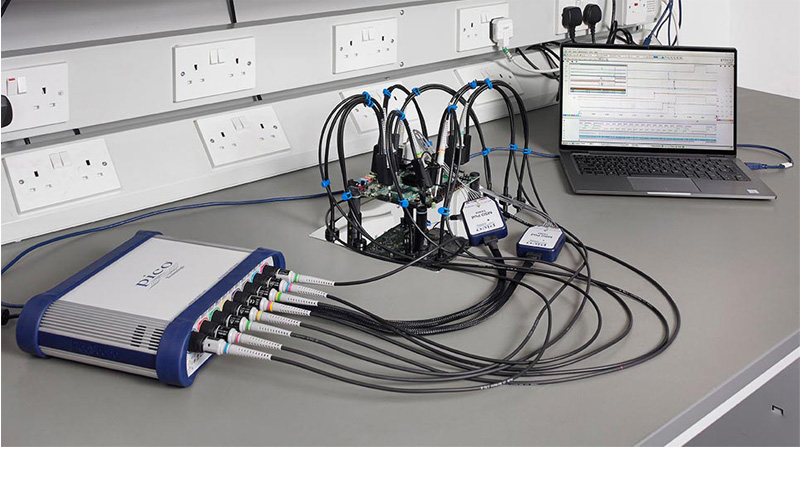
Power, portability, and performance
PicoScope 6000E 시리즈는 최대 8개의 아날로그 채널를 제공하며,또한 플러그인 8채널 TA369 MSO(혼합 신호 오실로스코프) 포드가 있는 옵션인 8개 또는 16개의 디지털 채널을 제공합니다. 고해상도 디스플레이 옵션을 통해 각 신호를 자세히 보고 분석할 수 있습니다.
PicoScope 소프트웨어는 설계, 연구, 테스트, 교육, 서비스 및 수리를 비롯한 다양한 응용 분야에 적합하며,놀라운 성능과 가성비 좋은 패키지를 제공합니다. PicoScope 소프트웨어는 스코프 가격에 포함되어 있으며 무료 다운로드 및 무료 업데이트가 가능하며 원하는 PC에 설치할 수 있으므로 스코프 없이 오프라인에서 데이터를 보고 분석할 수 있습니다.
High-end features as standard
추가 투자 금액을 거의 없으며, 스코프 내의 PC 소프트웨어와 펌웨어를 모두 업데이트할 수 있습니다. Pico 기술은 소프트웨어 다운로드를 통해 무료로 새로운 기능을 제공하는 오랜 역사를 가지고 있습니다. 놀라운 성능의 PicoScope의 스코프를 사용해보세요!
강력한 툴을 무한한 옵션으로 제공
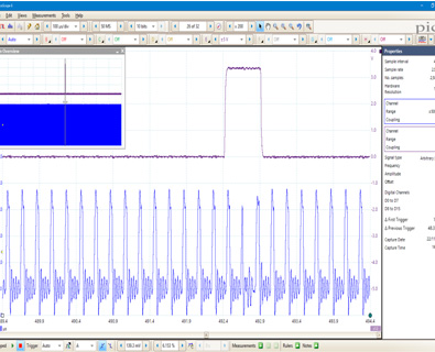
예를 들어, 빠른 트리거 모드를 사용하면 몇 밀리초 만에 10,000 파형을 수집할 수 있으며, 그 간격에 대한 데드 타임이 최소화됩니다. 이러한 파형을 수동으로 검색하는 것은 시간이 많이 걸리므로 원하는 파형을 선택하고 마스크 도구가 자동으로 스캔하도록 하십시오. 완료되면 측정을 통해 얼마나 많은 실패가 있는지 알 수 있으며 버퍼 네비게이터를 사용하면 좋은 파형은 숨겨두고 문제가 있는 것를 표시 할 수 있습니다.
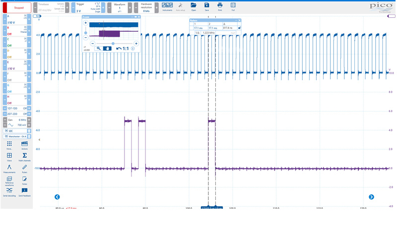
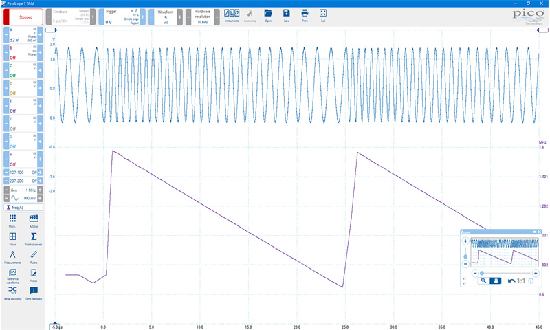
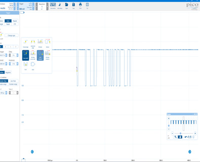
여기에 있는 스크린샷은 주파수와 시간을 변경한 그래프로 보여줍니다. 아마도 그래프로 변화하는 듀티 사이클을 그리기 원하시죠? 트리거 조건이 충족되면 파형을 디스크에 자동으로 저장하고 AWG에서 출력하는 것은 어떤가요? PicoScope를 사용해보시면, 앞에 질문에 답이 될 것입니다.
| [ Feature ] | |
|---|---|
FlexRes ? Pico FlexRes 가변 분해능 오실로스코프를 사용하면 샘플링 속도 또는 분해능을 최적화하도록 스코프 하드웨어를 재구성 할 수 있습니다. 즉, 디지털 신호를 볼 수있는 고속 (5GSa /s) 8 비트 오실로스코프 또는 오디오 작업 및 기타 아날로그 애플리케이션을 위한 고해상도 12 비트 오실로스코프로 하드웨어를 재구성 할 수 있습니다. 빠른 디지털 신호를 캡처 및 디코딩하거나 민감한 아날로그 신호에서 왜곡을 찾고 있는지 여부에 대한 올바른 선택은 FlexRes 오실로스코프입니다. FlexRes는 PicoScope 6824E에서 사용할 수 있습니다. PicoScope 6에 내장 된 디지털 신호 처리 기술인 해상도 향상은 스코프의 유효 수직 해상도를 16 비트로 더욱 향상시킬 수 있습니다. |
 |
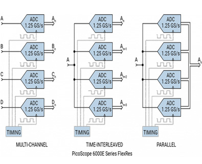 |
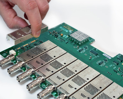
FlexRes- 사용 방법 대부분의 디지털 오실로스코프는 여러 8 비트 ADC를 인터리빙하여 높은 샘플링 속도를 얻습니다. 이 인터리빙 프로세스는 개별 ADC 코어보다 항상 동적 성능을 저하시키는 오류를 발생시킵니다. FlexRes 아키텍처는 서로 다른 시간 인터리브 및 병렬 조합으로 입력 채널에서 다중 고해상도 ADC를 사용하여 8 비트에서 샘플링 속도를 5GS / s로, 1.25GS / s에서 12 비트로 분해능을 최적화하거나 서로간 다른 조합으로 최적화합니다. 다이어그램은 4 개의 채널로 구성된 하나의 뱅크를 보여줍니다. PicoScope 6824E에는 두 개의 뱅크가 있습니다. 높은 신호 대 잡음비 증폭기 및 저잡음 시스템 아키텍처와 결합 된 FlexRes 기술은 높은 샘플링 속도로 최대 500MHz의 신호 또는 일반적인 8 비트 오실로스코프보다 16 배 높은 해상도의 저속 신호를 캡처하고 표시 할 수 있습니다. PicoScope 6 소프트웨어를 사용하면 해상도를 수동으로 설정하고 스코프를 자동 해상도 모드로 유지할 수 있습니다 (여기서 선택한 설정에 최적 해상도가 사용됨). |
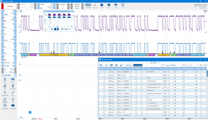
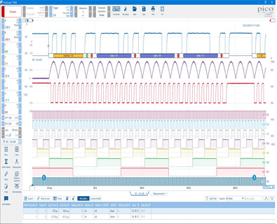
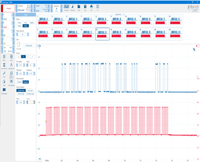
혼합 신호 측정 대부분의 벤치 탑 혼합 신호 오실로스코프는 최대 4 개의 아날로그 채널과 16 개의 디지털 입력을 제공합니다. 옵션 8 채널 TA369 MSO 포드를 장착하면 PicoScope 6000E 시리즈는 8 개의 아날로그 채널에 최대 16 개의 고성능 디지털 채널을 추가하여 아날로그 및 디지털 채널을 정확하게 시간에 동기시킬 수 있습니다. 디지털 채널 대역폭은 00MHz이며 1Gb/s에 해당하며 입력 커패시턴스가 3.5pF에 불과하므로 테스트중인 장치의 부하효과가 최소화됩니다. 병렬 또는 다중 직렬 버스에서 캡처 된 디지털 채널은 그룹화되어 버스로 표시 될 수 있으며 각 버스 값은 16 진, 2 진 또는 10 진수 또는 레벨 (DAC 테스트 용)로 표시됩니다. 아날로그 및 디지털 채널에서 고급 트리거를 설정할 수 있습니다. 디지털 입력은 또한 직렬 디코딩 기능 분석에 유용성을 확장합니다. 모든 아날로그 및 디지털 채널에서 직렬 데이터를 동시에 디코딩하여 여러 SPI, I²C, CAN 버스, LIN 버스 및 FlexRay 신호를 동시에 디코딩하는 등 최대 24 개의 데이터 채널을 제공 할 수 있습니다! |
 |
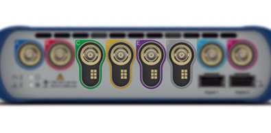 |
지능형 프로브 인터페이스 채널 C에서 F에 지능형 프로브 인터페이스를 갖춘 PicoScope 6000E 시리즈는 연결의 용이성과 DUT의 낮은 부하효과을 위해 Low 프로파일 기계적 설계로 혁신적인 액티브 프로브 지원하게 될것입니다. |
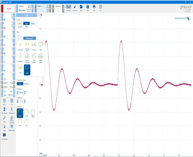
신호 무결성 정밀한 프런트 엔드 설계 및 차폐는 노이즈, 누화 및 고조파 왜곡을 줄입니다. PicoScope 6000E 시리즈 오실로스코프는 최대 60dB SFDR의 동적 성능을 나타냅니다. PicoScope를 사용하면 회로를 프로브할 때 화면에 표시되는 파형을 신뢰할 수 있습니다. |
 |
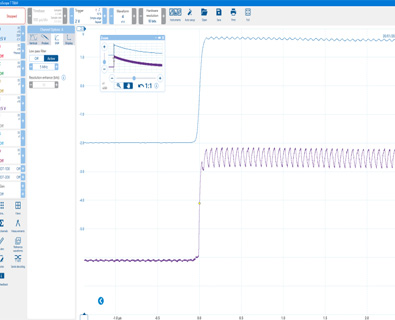 |
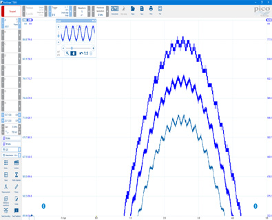
낮은 레벨 신호를 위한 고해상도 12 비트 해상도의 PicoScope 6824E는 높은 줌 비율로 낮은 레벨의 신호를 표시 할 수 있습니다. 이를 통해 더 큰 DC 또는 저주파 전압에 중첩 된 노이즈 및 리플과 같은 기능을 보고 측정 할 수 있습니다. 또한 각 채널에서 저역 통과 필터링 컨트롤을 독립적으로 사용하여 노이즈를 숨기고 기본 신호를 표시 할 수 있습니다. |
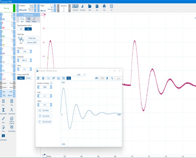
임의 파형/함수 발생기(AWG) PicoScope 6000E 스코프에는 삼각형, DC 레벨, 화이트 노이즈, PRBS 및 기타 낮은 주파수에서 가능한 기타 파형을 갖춘 내장형 50MHz 함수 (사인파 및 구형파) 발생기가 있습니다. 레벨, 오프셋 및 주파수를 설정하는 기본 제어뿐만 아니라 고급 제어을 사용하여 다양한 주파수 범위를 스윕 할 수 있습니다. 스펙트럼 피크 홀드 옵션과 함께 사용하면 증폭기 및 필터 응답을 테스트하는 강력한 도구가 됩니다. 트리거 도구를 사용하면 스코프 트리거링 또는 마스크 한계 테스트 실패와 같은 다양한 조건이 충족 될 때 하나 이상의 파형 사이클을 출력 할 수 있습니다. 두 모델 모두 14 비트 200 MS/s 임의 파형 발생기(AWG)를 포함합니다. 여기에는 가변 샘플 클럭이 있어 고정 클럭 발생기에서 볼 수 있는 파형 에지의 지터를 방지하고 100µHz까지 정확한 주파수를 생성 할 수 있습니다. AWG 파형은 내장 편집기를 사용하여 생성 또는 편집하거나 오실로스코프 트레이스에서 가져 오거나 스프레드 시트에서 불러온 .csv 파일로 내보낼 수 있습니다. |
 |
 |
디지털 트리거링 아키텍처 많은 디지털 오실로스코프는 여전히 비교군에 기초한 아날로그 트리거 아키텍처를 사용한다. 이 경우 항상 보정할 수 없는 시간과 진폭 오류가 발생하고 높은 대역폭에서 트리거 감도를 제한하는 경우가 많습니다. 1991년 Pico는 실제 디지털화된 데이터를 사용하여 완전한 디지털 트리거링을 처음 사용하였다. 이 기법은 트리거 오류를 줄이고 오실로스코프가 최대 대역폭에서도 가장 작은 신호에 트리거할 수 있게 해준다. 트리거 레벨과 이력은 높은 정밀도와 분해능으로 설정할 수 있습니다 |
고급 트리거 PicoScope 6000E 시리즈는 펄스 폭, 런트 펄스, 윈도우 , 로직 및 드롭아웃을 포함한 업계 최고의 고급 트리거 유형 세트를 제공한다. MSO 작업 중에 사용할 수 있는 디지털 트리거를 사용하면 16개의 디지털 입력 중 어느 또는 모든 것이 사용자 정의 패턴과 일치하는 경우 범위를 트리거할 수 있습니다. 각 채널에 대한 조건을 개별적으로 지정하거나 육각형 또는 이진 값을 사용하여 한 번에 모든 채널에 대한 패턴을 설정할 수 있습니다. 로직 트리거를 사용하여 디지털 트리거를 아날로그 입력의 에지 또는 창 트리거와 결합할 수도 있습니다(예: 클럭된 병렬 버스의 데이터 값에 대해 트리거) |
 |
 |
하드웨어 가속 엔진 HAL4 일부 오실로스코프는 Deep Memory을 가능하게 할 때 어려움을 겪습니다. 화면 업데이트 속도가 느려지고 컨트롤이 응답하지 않습니다. PicoScope 6000E 시리즈는 오실로스코프 내부의 전용 4세대 하드웨어 가속(HAL4) 엔진을 사용하여 이러한 제한을 막을 수 있습니다. 대규모 병렬 설계로 PC 화면에 표시할 파형 이미지를 효과적으로 생성하고 초당 25억 개의 샘플을 연속 캡처하고 화면에 표시할 수 있습니다. 하드웨어 가속 엔진은 USB 연결 또는 PC 프로세서 성능이 병목 현상에 대한 우려를 제거합니다. |
타임 스탬프 PicoScope 6000E 시리즈는 하드웨어 기반 트리거 타임스탬프를 제공합니다. 각 파형은 이전 파형의 샘플 간격으로 시간 스탬프를 찍을 수 있습니다. 빠른 트리거 재정렬 시간은 300ns(일반)까지 가능합니다. |
 |
아래의 table에서 PICOSCOPE® 6000E SERIES 의 모델을 확인하세요.
| Model | PicoScope | ||||
|---|---|---|---|---|---|
| Bandwidth (–3 dB) | 300 MHz | 500 MHz | 750 MHz | 1 GHz | 3 GHz |
| 4- channel 8-bit | 6403E | 6404E | 6405E | 6406E | |
| 4-channel FlexRes | 6424E | 6425E | 6426E | 6428E-D | |
| 8-channel 8-bit | 6804E | ||||
| 8-channel FlexRes | 6824E | ||||
| Vertical (analog channels) | |||||
|---|---|---|---|---|---|
| Bandwidth (–3 dB) | 300 MHz | 500 MHz | 50 Ω ranges: 750 MHz 1 MΩ ranges: 500 MHz |
50 Ω ranges: 1 GHz 1 MΩ ranges: 500 MHz |
50 Ω range: 3 GHz[1] |
| Rise time | < 1.3 ns | < 850 ps | 50 Ω ranges: < 475 ps 1 MΩ ranges: < 850 ps |
50 Ω ranges: < 350 ps 1 MΩ ranges: < 850 ps |
50 Ω range: 150 ps[1] |
| [1] ±500 mV range, 2.5 GHz/180 ps due to 3600 V/μs maximum slew rate | |||||
| Bandwidth limiter | 20 MHz. Software-switchable. | 20 MHz or 200 MHz. Software-switchable. | N/A | ||
| Vertical resolution | FlexRes models: 8, 10 or 12 bits Other models: 8 bits |
||||
| LSB size (quantization step size) |
8-bit mode: < 0.4% of input range
|
||||
| Enhanced vertical resolution | Up to 4 extra bits beyond ADC resolution | ||||
| Input connector | BNC(f). x10 readout-pin compatible. Intelligent Probe Interface on all channels (4-channel models) or on channels C to F (8-channel models). | ||||
| Input ranges (50 Ω ranges) |
±10 mV to ±5 V as above | ±50 mV ±100 mV ±200 mV ±500 mV |
|||
| Input ranges (1 MΩ ranges) |
±10 mV, ±20 mV, ±50 mV, ±100 mV, ±200 mV, ±500 mV, ±1 V, ±2 V, ±5 V, ±10 V, ±20 V | N/A | |||
| Input sensitivity (50 Ω ranges) |
2 mV/div to 1 V/div (10 vertical divisions) | 10 mV/div to 100 mV/ div (10 vertical divisions) |
|||
| Input sensitivity (1 MΩ ranges) |
2 mV/div to 4 V/div (10 vertical divisions) | N/A | |||
| Input coupling (50 Ω ranges) |
DC |
||||
| Input coupling (1 MΩ ranges) |
AC / DC | N/A | |||
| Input characteristics | 50 Ω ±2% | 50 Ω ±3% | 50 Ω ±1% | ||
| 1 MΩ ±0.5% ∥ 12 pF ±1 pF | N/A | ||||
| DC gain accuracy (8-bit models) | ±(1.5% of signal + 1 LSB) | N/A | |||
| DC gain accuracy (FlexRes models) | N/A | ±(0.5% of signal + 1 LSB) | ±(1% of signal + 1 LSB) | ±(2% of signal + 1 LSB) | |
| DC offset accuracy | ±(1% of full scale + 250 μV) | ±(2% of full scale + 500 μV) |
|||
| Can be improved by using the “zero offset” function in PicoScope. | |||||
| Analog offset range 50 Ω (vertical position adjustment) |
±1.25 V (±10 mV to ±1 V ranges) ±20 V (±2 V to ±20 V ranges) |
±125 mV (±10 mV to ±100 mV ranges) ±1.25 V (±200 mV to ±1 V ranges) ±5 V (±2 V and ±5 V ranges) |
±400 mV (±50 mV to ±500 mV ranges) |
||
| Analog offset range 1 MΩ (vertical position adjustment) |
±1.25 V (±10 mV to ±1 V ranges) ±20 V (±2 V to ±20 V ranges) |
N/A |
|||
| Analog offset control accuracy | ±0.5% of offset setting, additional to basic DC offset accuracy | ||||
| Overvoltage protection |
50 Ω ranges: 5.5 V RMS max, ± 10V pk max |
3 V RMS max, ±6 V pk max |
|||
| 1 MΩ ranges: ±100 V (DC + AC peak) up to 10 kHz | N/A | ||||
| Vertical (digital channels, with optional TA369 8-channel MSO pods) | |||||
|---|---|---|---|---|---|
| Input channels | 16 channels (2 ports of 8 channels each) | ||||
| Maximum detectable input frequency | 500 MHz (1 Gb/s) | ||||
| Minimum detectable pulse width | 1 ns | ||||
| Input connector (probe tip) | Staggered signal and ground sockets for each channel, to accept 0.64 – 0.89 mm round or 0.64 mm square pin, 2.54 mm pitch | ||||
| Input characteristics | 101 kΩ ±1% ∥ 3.5 pF ±0.5 pF | ||||
| Maximum input voltage at probe tip | ±40 V up to 10 MHz, derated linearly to ±5 V at 500 MHz | ||||
| Threshold range and resolution | ±8 V in approx. 5 mV steps | ||||
| Threshold grouping | PicoScope software: Two independent threshold controls, one per 8-channel port PicoSDK: Individual threshold for each channel |
||||
| Threshold selection | TTL, CMOS, ECL, PECL, user-defined | ||||
| Threshold accuracy | ±(100 mV + 3% of threshold setting) | ||||
| Minimum input voltage swing (at maximum frequency) | 400 mV peak to peak | ||||
| Hysteresis (at DC) | PicoScope software: Fixed hysteresis approx. 100 mV PicoSDK: selectable per port; approx. 50 mV, 100 mV, 200 mV or 400 mV |
||||
| Minimum input slew rate | No minimum slew rate requirement | ||||
| Horizontal | ||||||
|---|---|---|---|---|---|---|
| Maximum sampling rate (real-time, 8-bit) | ||||||
| 1 analog channel | 5 GS/s | 10 GS/s | ||||
| 1-2 MSO pods, no analog channels | 5 GS/s | |||||
| 1 analog channel plus 1 MSO pod | 5 GS/s | |||||
| Up to 2 channels, 0 or 1 analog | 5 GS/s | 4-ch models: 5 GS/s[2] 8-ch models: 5 GS/s[4] |
5 GS/s[2] | |||
| Up to 4 channels, 2 analog | 2.5 GS/s[2] | 4-ch models: 2.5 GS/s 8-ch models: 2.5 GS/s[3] |
2.5 GS/s | |||
| Up to 4 channels, 3 or 4 analog | 1.25 GS/s | 4-ch models: 2.5 GS/s 8-ch models: 2.5 GS/s[3] |
2.5 GS/s | |||
| Up to 8 channels | 1.25 GS/s | |||||
| More than 8 channels | N/A | 625 MS/s | N/A | |||
| Maximum sampling rate (real time, 10-bit, FlexRes models only) | ||||||
| 1 channel | N/A | 5 GS/s | ||||
| Up to 2 channels | 6824E: 2.5 GS/s[3] 6424E: 2.5 GS/s |
2.5 GS/s | ||||
| Up to 4 channels | 1.25 GS/s | |||||
| Up to 8 channels | 625 MS/s | |||||
| More than 8 channels | 6424E: N/A 6824E: 312.5 MS/s |
N/A | ||||
| Maximum sampling rate (real time, 12-bit, up to 2 channels, FlexRes models only) | ||||||
| 1 to 2 analog channels plus 0 to 2 digital ports | N/A | 6824E: 1.25 GS/s[4] 6424E: 1.25 GS/s[2] |
1.25 GS/s[2] | |||
| Max. sampling rate, USB 3.0 streaming mode (split between active channels, PC dependent) | ||||||
| PicoScope software | ~20 MS/s | |||||
| PicoSDK | ~312 MS/s | ~312 MS/s (8-bit mode) ~156 MS/s (10/12-bit modes, FlexRes models) |
||||
| Max. sampling rate to on-device buffer (continuous USB streaming of raw or downsampled data, split between enabled channels) | ||||||
| PicoSDK only | 1.25 GS/s | 1.25 GS/s (8-bit mode) 625 MS/s (10/12-bit modes, FlexRes models) |
||||
| Capture memory (shared between active channels) | ||||||
| 8-bit models | 1 GS | 2 GS | ||||
| FlexRes models, 8-bit mode | N/A | 4 GS | ||||
| FlexRes models, 10- and 12-bit modes | 2 GS | |||||
| Maximum single capture duration at maximum sampling rate | ||||||
| PicoScope software | 200 ms | |||||
| 8-bit models, PicoSDK | 200 ms | 400 ms | ||||
| 8-bit, PicoSDK, FlexRes models | N/A | 800 ms | ||||
| 10-bit, PicoSDK, FlexRes models | N/A | 400 ms | ||||
| 12-bit, PicoSDK, FlexRes models | 1600 ms | |||||
| Capture memory (continuous streaming) | 100 MS in PicoScope software. Buffering using full device memory when using PicoSDK, no limit on total duration of capture. | |||||
| Waveform buffer (number of segments, PicoScope software) | 10 000 | |||||
| Waveform buffer (number of segments, PicoSDK) | 1 000 000 | 2 000 000 | ||||
| Timebase ranges | 1 ns/div to 5000 s/div | |||||
| Initial timebase accuracy | ±2 ppm | |||||
| Timebase drift | ±1 ppm/year | |||||
| ADC sampling | Simultaneous sampling on all enabled analog and digital channels | |||||
[2] No more than one channel from each of AB and CD.
[3] No more than one channel from each of AB, CD, EF and GH.
[4] No more than one channel from each of ABCD and EFGH.
| External reference clock | |||||
|---|---|---|---|---|---|
| Input characteristics | Hi-Z, AC coupled (> 1 kΩ at 10 MHz) | ||||
| Input frequency range | 10 MHz ±50 ppm | ||||
| Input connector | Rear-panel BNC(f), dedicated | ||||
| Input level | 200 mV to 3.3 V peak to peak | ||||
| Overvoltage protection | ±5 V peak max | ||||
| The external reference clock synchronizes both the scope and the AWG. | |||||
| Dynamic performance (typical; analog channels) | |||||
|---|---|---|---|---|---|
| 300 MHz | 500 MHz | 750 MHz | 1 GHz | 3 GHz | |
| Crosstalk | 1200:1 (±10 mV to ±1 V ranges) 300:1 (±2 V to ±20 V ranges) |
2500:1 (±10 mV to ±1 V ranges) 600:1 (±2 V to ±20 V ranges) |
1000:1 up to 500 MHz 200:1 up to 3 GHz |
||
| from DC to bandwidth of victim channel, equal voltage ranges | |||||
| Harmonic distortion, 8-bit mode | –50 dB at 1 MHz full scale | ||||
| Harmonic distortion, 10/12-bit mode, FlexRes models | –60 dB at 1 MHz full scale, typical | –60 dB | |||
| SFDR, 8-bit models | > 50 dB on ±50 mV to ±20 V ranges | N/A | |||
| SFDR, FlexRes models | > 60 dB on ±50 mV to ±20 V ranges | > 60 dB on ±50 mV to ±500 mV ranges |
|||
| Noise, 8-bit models | < 200 μV RMS on most sensitive range | N/A | |||
| Noise, FlexRes models | < 150 μV RMS on most sensitive range | < 700 μV rms, ±50 mV range |
|||
| Linearity, 8-bit mode | < 2 LSB | ||||
| Linearity, 10-bit mode | N/A | < 4 LSB (FlexRes models) | < 4 LSB | ||
| Bandwidth flatness | (+0.3 dB, –3 dB) from DC to full bandwidth | (+1 dB, −3 dB) from DC to full bandwidth |
|||
| Low frequency flatness | < ±3% (or ±0.3 dB) from DC to 1 MHz | ||||
| Triggering (main specifications) | |||||
|---|---|---|---|---|---|
| Source | Any analog channel, AUX trigger, plus digital ports with optional TA369 MSO pods | ||||
| Trigger modes | None, auto, repeat, single, rapid (segmented memory) | ||||
| Advanced trigger types (analog channels) | Edge (rising, falling, rising-or-falling), window (entering, exiting, entering-or-exiting), pulse width (positive or negative or either pulse), window pulse width (time inside, outside window or either), level dropout (including high/low or either), window dropout (including inside, outside or either), interval, runt (positive or negative), transition time (rise/fall), logic Logic trigger capabilities: AND or OR function of any number of trigger sources (analog channels, MSO ports and aux input) NAND/NOR/XOR/XNOR of up to four trigger sources plus aux input User-defined Boolean function of up to four trigger sources plus aux input (PicoSDK only) |
||||
| Trigger sensitivity (analog channels) | Digital triggering provides 1 LSB accuracy up to full bandwidth of scope with adjustable hysteresis | ||||
| Advanced trigger types (digital channels, with optional MSO pods) | Edge, pulse width, dropout, interval, pattern, logic (mixed signal) | ||||
| Pre-trigger capture | Up to 100% of capture size | ||||
| Post-trigger delay | PicoScope software: 0 to > 4 x 10⁹ samples, settable in 1 sample steps (delay range at fastest sample rate of 0.8 s in 200 ps steps) PicoSDK: 0 to > 1012 samples, settable in 1 sample steps (delay range at fastest sample rate of > 200 s in 200 ps steps) |
||||
| Rapid trigger mode rearm time | 700 ns max, 300 ns typical (single channel, 5 GS/s) | ||||
| Maximum trigger rate | PicoScope software: 40 000 waveforms in 12 ms; PicoSDK: Number of waveforms up to memory segment count, at a rate of 6 million waveforms per second. | ||||
| Trigger time-stamping | Each waveform is timestamped in sample intervals (PicoSDK) or time (PicoScope software) from previous waveform. The time resets when any settings are changed. |
||||
| Auxiliary trigger input | |||||
|---|---|---|---|---|---|
| Connector type | Rear-panel BNC(f) | ||||
| Trigger types (triggering scope) | Edge, pulse width, dropout, interval, logic | ||||
| TRigger types (triggering AWG) | Rising edge, falling edge, gate high, gate low | ||||
| Input bandwidth | > 10 MHz | ||||
| Input characteristics | 2.5 V CMOS Hi-Z input, DC coupled | ||||
| Threshold | Fixed threshold, 1.25 V nominal to suit 2.5 V CMOS | ||||
| Hysteresis | 1 V max (VIH < 1.75V, VIL > 0.75V) | ||||
| Overvoltage protection | ±20 V peak max | ||||
| Function generator | |||||
|---|---|---|---|---|---|
| Standard output signals | Sine, square, triangle, DC voltage, ramp up, ramp down, sinc, Gaussian, half-sine | ||||
| Output frequency range | Sine/square waves: 100 μHz to 50 MHz Other waves: 100 μHz to 10 MHz |
||||
| Output frequency accuracy | Oscilloscope timebase accuracy ± output frequency resolution | ||||
| Output frequency resolution | 0.002 ppm | ||||
| Sweep modes | Up, down, dual with selectable start/stop frequencies and increments | ||||
| Sweep frequency range | Sine/square waves: 0.075 Hz to 50 MHz Other waves: 0.075 Hz to 10 MHz Swept frequencies down to 100 μHz are possible using PicoSDK with some restrictions |
||||
| Sweep frequency resolution |
PicoScope 7: 0.075 Hz PicoSDK: Sweep frequency resolution down to 100 μHz is possible with some restrictions |
||||
| Triggering | Free-run, or from 1 to 1 billion counted waveform cycles or frequency sweeps. Triggered from scope trigger, aux trigger or manually. | ||||
| Gating | Waveform output can be gated (paused) via aux trigger input or software | ||||
| Pseudorandom output signals | White noise, selectable amplitude and offset within output voltage range Pseudorandom binary sequence (PRBS), selectable high and low levels within output voltage range, selectable bit rate up to 50 Mb/s |
||||
| Output voltage range | ±5 V into open circuit; ±2.5 V into 50 Ω | ||||
| Output voltage adjustment | Signal amplitude and offset adjustable in < 1 mV steps within overall range | ||||
| DC accuracy | ±(0.5% of output voltage + 20 mV) | ||||
| Amplitude flatness | Sine wave into 50 Ω: < 2.0 dB to 50 MHz Square: < 0.5 dB to 50 MHz Other waveforms: < 1.0 dB to 1 MHz, < 2.0 dB to 10 MHz (except sinc) |
||||
| SFDR | 70 dB (10 kHz 1 V peak to peak sine into 50 Ω) | ||||
| Output noise | < 700 μV RMS (DC output, filter enabled, into 50 Ω) | ||||
| Output resistance | 50 Ω ±3% | ||||
| Connector type | Rear-panel BNC | ||||
| Overvoltage protection | ±20 V peak max | ||||
| Arbitrary waveform generator | |||||
|---|---|---|---|---|---|
| Update rate | Variable from < 1 S/s to 200 MS/s with < 0.002 ppm resolution | ||||
| Buffer size | 40 kS | ||||
| Vertical resolution | 14 bits (output step size < 1 mV) | ||||
| Analog filters | 50 MHz selectable filter (5-pole, 30 dB/octave) | ||||
| Bandwidth (−3 dB) | No filter: 100 MHz Filtered: 50 MHz |
||||
| Rise time (10% to 90%) | No filter: 3.5 ns Filtered: 6 ns |
||||
Sweep modes, triggering, frequency accuracy and resolution, voltage range and accuracy and output characteristics as for function generator.
| Probe support | |||||
|---|---|---|---|---|---|
| Intelligent probe interface | Intelligent probe interface on four channels supporting A3000 Series active probes. Probe interface supplies power and controls the probe. | ||||
| Probe detection | Automatic detection of Pico P2036, P2056 x10 passive oscilloscope probes, and A3000 Series active probes. | ||||
| Probe compensation pin | 1 kHz, 2 V peak to peak square wave, 600 Ω | ||||
| Probe compensation pin rise time | < 50 ns | ||||
| Spectrum analyzer | |||||
|---|---|---|---|---|---|
| Frequency range | DC to oscilloscope's rated bandwidth | ||||
| Display modes | Magnitude, average, peak hold | ||||
| Y axis | Logarithmic (dbV, dBu, dBm, arbitrary dB) or linear (volts) | ||||
| X axis | Linear or logarithmic | ||||
| Windowing functions | Rectangular, Gaussian, triangular, Blackman, Blackman–Harris, Hamming, Hann, flat-top | ||||
| Number of FFT points | Selectable from 128 to 1 million in powers of 2 | ||||
| Math channels | |||||
|---|---|---|---|---|---|
| Functions | −x, x+y, x−y, x*y, x/y, x^y, sqrt, exp, ln, log, abs, norm, sign, sin, cos, tan, arcsin, arccos, arctan, sinh, cosh, tanh, delay, average, frequency, derivative, integral, min, max, peak, duty, highpass, lowpass, bandpass, bandstop, coupler, top, base, amplitude, positive overshoot, negative overshoot |
||||
| Operands | A to H (input channels), T (time), reference waveforms, pi, 1D0 to 2D7 (digital channels), constants | ||||
| Automatic measurements | |||||
|---|---|---|---|---|---|
| Scope mode | AC RMS, cycle time, DC average, duty cycle, edge count, fall time, falling edge count, falling rate, frequency, high pulse width, low pulse width, maximum, minimum, negative duty cycle, peak to peak, rise time, rising edge count, rising rate, true RMS, top, base, amplitude, positive overshoot, negative overshoot, phase |
||||
| Spectrum mode | Frequency at peak, amplitude at peak, average amplitude at peak, total power, THD%, THD dB, THD+N, SINAD, SNR, IMD | ||||
| Statistics | Minimum, maximum, average, standard deviation | ||||
| DeepMeasure™ | |||||
|---|---|---|---|---|---|
| Parameters | Cycle number, cycle time, frequency, low pulse width, high pulse width, duty cycle (high), duty cycle (low), rise time, fall time, undershoot, overshoot, max. voltage, min. voltage, voltage peak to peak, start time, end time |
||||
| Serial decoding | |||||
|---|---|---|---|---|---|
| Protocols | 1-Wire, ARINC 429, BroadRReach, CAN, CAN FD, CAN J1939, CAN XL, DALI, DCC, DMX512, Ethernet 10BASE-T, Extended UART, Fast Ethernet 100BASE-TX, FlexRay, I2C, I2S, I3C BASIC v1.0, LIN, Manchester, MIL-STD-1553, MODBUS ASCII, MODBUS RTU, NMEA-0183, Parallel Bus, PMBus, PS/2, PSI5 (Sensor), Quadrature, RS232/UART, SBS Data, SENT Fast, SENT Slow, SENT SPC, SMBus, SPI-MISO/MOSI, SPI-SDIO, USB (1.0/1.1), Wind Sensor |
||||
| Mask limit testing | |||||
|---|---|---|---|---|---|
| Statistics | Pass/fail, failure count, total count | ||||
| Mask creation | Auto-generated from waveform or imported from file | ||||
| Display | |||||
|---|---|---|---|---|---|
| Display modes | Scope, XY scope, persistence, spectrum | ||||
| Interpolation | Linear or sin(x)/x | ||||
| >Persistence modes | Time, frequency, fast | ||||
| Output functions | Copy to clipboard, print | ||||
| Output file formats | csv, mat, pdf, png, psdata, pssettings, txt | ||||
| Software | |||||
|---|---|---|---|---|---|
| Windows software (64-bit)>[5] |
PicoScope 7, PicoLog 6, PicoSDK (Users writing their own apps can find example programs for all platforms on the Pico Technology organization page on GitHub). PicoScope 6 may be available for older operating systems supporting products purchased up to 2022.
|
||||
| macOS software (64-bit)>[5] | PicoScope 7, PicoLog 6 and PicoSDK | ||||
| Linux software (64-bit)>[5] |
PicoScope 7 software and drivers, PicoLog 6 (including drivers) |
||||
| Raspberry Pi 4B (Raspberry Pi OS)[5] |
PicoLog 6 (including drivers) See Linux Software and Drivers to install drivers only |
||||
| Languages supported, PicoScope software | English-US, English-UK, Bulgarian, Czech, Danish, German, Greek, Spanish, French, Korean, Croatian, Italian, Hungarian, Netherlands Dutch, Japanese, Norwegian, Polish, Portuguese- Brazil, Portuguese, Romanian, Russian, Slovene, Serbian, Finnish, Swedish, Turkish, Simplified Chinese, Traditional Chinese |
||||
| Languages supported, PicoLog | Simplified Chinese, Dutch, English (UK), English (US), French, German, Italian, Japanese, Korean, Russian, Spanish | ||||
| PC requirements | Processor, memory and disk space: as required by the operating system Ports: USB 3.0 (recommended) or 2.0 (compatible) |
||||
| General | |||||
|---|---|---|---|---|---|
| Package contents |
|
||||
| PC connectivity | USB 3.0 SuperSpeed (USB 2.0 compatible) | ||||
| USB connector | Type B | ||||
| Power requirements | 12 V DC from supplied PSU. Up to 5 A (scope only) or 7 A including scope-powered accessories | ||||
| Ground terminal | Functional ground terminal accepting wire or 4 mm plug, rear-panel | ||||
| Thermal management | Automatic fan speed control for low noise | ||||
| Dimensions | 245 x 192 x 61.5 mm | ||||
| Weight | 2.2 kg (scope only) 5.6 kg (in carry case with PSU and cables) |
||||
| Ambient temperature range | Operating: 0 to 40 °C 15 to 30 °C after 20-minute warm-up Storage: –20 to +60 °C |
||||
| Humidity range | Operating: 5 to 80 %RH non-condensing Storage: 5 to 95 %RH non-condensing |
||||
| Altitude range | Up to 2000 m | ||||
| Pollution degree | EN 61010 pollution degree 2: “only nonconductive pollution occurs except that occasionally a temporary conductivity caused by condensation is expected” | ||||
| Safety compliance | Designed to EN 61010-1:2010 + A1:2019 | ||||
| EMC compliance | Tested to EN61326-1:2013 and FCC Part 15 Subpart B | ||||
| Environmental compliance | RoHS, REACH, WEEE | ||||
| Warranty | - | ||||
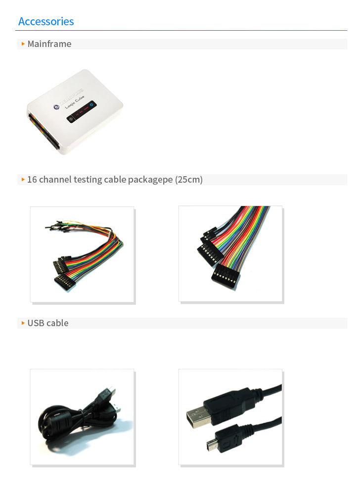
악세사리