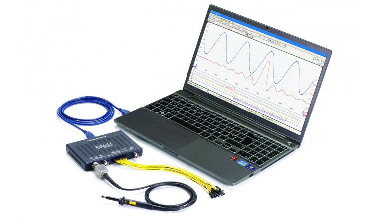
PICOSCOPE® 2000 SERIES
USB oscilloscopes & mixed signal oscilloscopesLike a benchtop oscilloscope, only smaller and better
고급 오실로스코프 디스플레이
모든PicoScope 2000의 핵심은 고급 오실로스코프로, 기대할 수 있는 모든것을 제공
Oscilloscope display showing zoom, rulers and measurements
로직 분석 / 혼합 신호
피코스코프 2000 시리즈는 혼합 신호를 포함하는 모델로 16 디지털 신호 입력 포트가 존재하여 아날로그 신호와 디지털 신호를 동시에
확인할 수 있습니다.
디지털 입력은 개별적으로나 2진수 그룹으로 디스플레이가 가능하며, 10진수 또는 16진수를 버스 스타일로 디스플레이가 가능합니다.
-5V ~ +5V에서 부터 분리된 로직 임계값은 각각 8비트 입력 포트로 정의 될 수 있습니다. 디지털 트리거는 모든 입력에서 선택적 전환과 결합된 모든 비트 패턴으로 활성화될 수 있습니다. 고급 로직 트리거는 아날로그 혹은 디지털 입력 채널로 세팅이 가능하며, 복잡한 혼합신호 트리거링을 둘다 사용하는것이 가능합니다.
디지털 입력은 직렬 디코딩 옵션에 추가 전원을 공급해 줍니다.
아날로그 채널과 디지털 채널 동시에 직렬 디코딩이 가능하며, 최대 18 데이터 채널을 제공합니다.
예를들어 다중SPI, I²C, CAN 버스, LIN 버스, FlexRay가 모든신호를 같은 시간에 디코드가 가능합니다.
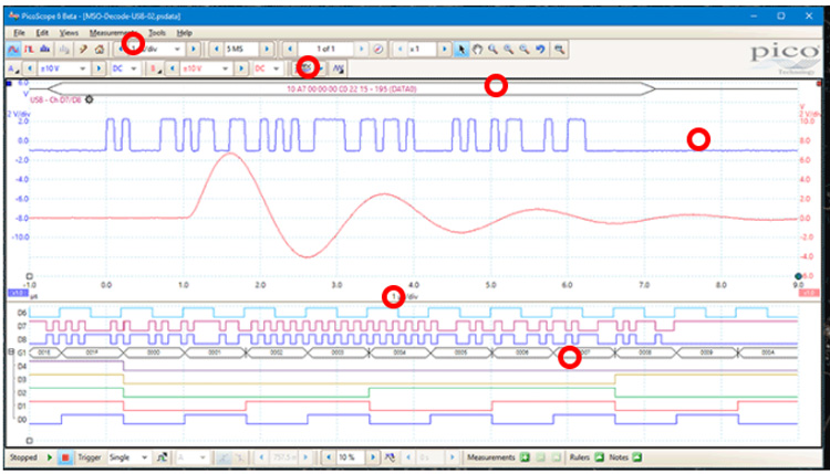
오실로스코프 혼합 신호 / 로직 분석기 (빨간색 원으로 표시)
직렬 버스 디코딩, 프로토콜 분석
PicoScope는 1-wire, ARNIC 429, CAN, DDC, DMX512, 이더넷, FlexRay, I²C, I²S, LIN, PS/2, SENT, SPI, UART (RS-232 / RS-422 /
RS-485), 그리고 USB 1.1을 기본으로 디코딩할 수 있으며, 더 많은 프로토콜 개발과 향후엔 무료 소프트웨어 업그레이드로 사용 가능합니다.
여러 프로토콜들은 캡쳐되거나 디코드될 수 있으며, 사용 가능한 채널수만 제한이됩니다.(MSO모델은 18채널). 브리지를 통한 데이터 흐름을 관찰하는 기능은 놀라울정도로 강력합니다.
딥 메모리 버퍼는 PicoScope 2000B모델이 수천 프레임의 데이터를 캡쳐하고 디코딩할 수 있으므로 직렬 디코딩에 이상적인 제품으로 만들어 줍니다.
여러 프로토콜들은 캡쳐되거나 디코드될 수 있으며, 사용 가능한 채널수만 제한이됩니다.(MSO모델은 18채널). 브리지를 통한 데이터 흐름을 관찰하는 기능은 놀라울정도로 강력합니다.
딥 메모리 버퍼는 PicoScope 2000B모델이 수천 프레임의 데이터를 캡쳐하고 디코딩할 수 있으므로 직렬 디코딩에 이상적인 제품으로 만들어 줍니다.
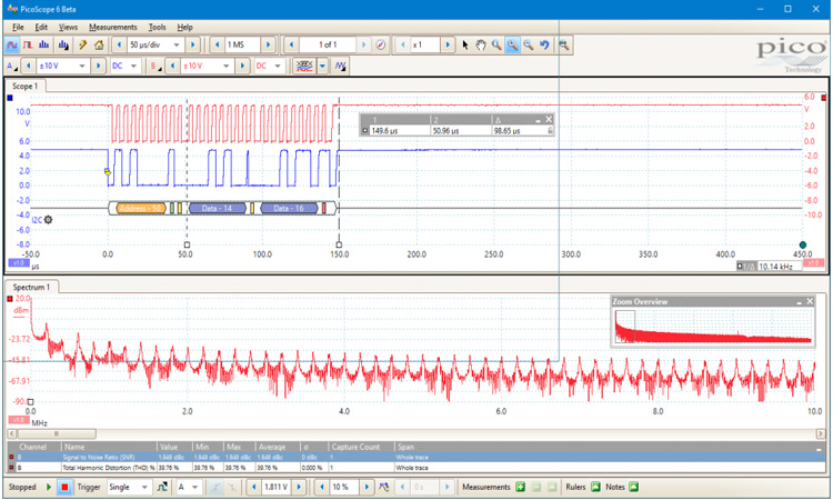
FFT 스펙트럼 분석기
스펙트럼 뷰는 주파수에대한 진폭을 표시합며, 오실로스코프 뷰에 숨겨져있는 세부정보를 공개합니다. 이것은 신호의 노이즈, 누화, 왜곡을
찾는것에 굉장히 이상적입니다.
같은 데이터의 오실로스코프 뷰를 스펙트럼 뷰와 함께 디스플레이가 가능합니다. 자동 주파수 영역 측정의 포괄적인 세팅은 디스플레이에 추가될 수 있으며, tdD, tdD+N, SNR, SINAD 와 IMD를 포함합니다.
마스크 한계 테스트는 스펙트럼에 반응하고 심지어 AWG도 사용 가능하며 스펙트럼모드로 스윕 스칼러 네트워크 분석도 수행 가능합니다. 100만 포인트의 PicoScope 2000B 모델과 함께 PicoScope 2000B모델을 사용하면 최대 백만 포인트의 FFT를 밀리초 단위로 계산하여 탁월한 주파수 분해능을 제공합니다. FFT포인트가 증가하면 노이즈가 낮아져 숨겨진 신호를 찾을 수 있습니다.
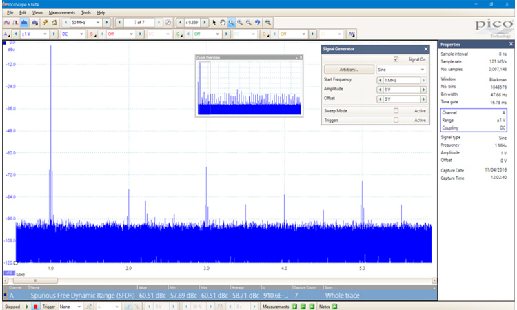
FFT포인트수를 100만으로 늘리게되면 주파수 분해능이 증가하고 노이즈 플로어가 줄어듭니다.
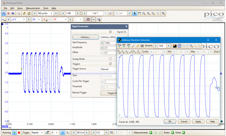
임의 파형 발생기(AWG)와 함수발생기
모든 PicoScope 2000시리즈의 오실로스코프는 함수발생기와 임의파형 발생기(AWG)기능을 사용이 가능하여 전면 BNC패널을 통하여
출력 신호를 확인할 수 있습니다.
함수발생기는 사인파, 구형파, 삼각파와 DC레벨 파형, 더 많은 파형들을 생성 가능하며, AWG를 사용하면 데이터 파일에서 사용자 정의 파형을 가져오거나 내장 그래픽 AWG 편집기를 사용하여 파형 생성 및 수정이 가능합니다.
레벨 뿐만 아니라 오프셋과 주파수 컨트롤도, 고급 옵션을 통해 다양한 주파수 범위를 쓸 수 있습니다. 고급 스펙트럼 모드, 피크 홀드를 포함한 옵션, 평균과 선형/로그 축, 증폭기와 필터 응답 테스팅에 매우 적합합니다.
PicoScope 2000B 모델은 트리거 옵션이 있어 스코프 트리거링 혹은 마스크 한계 테스트 실패 같은 다양한 조건이 충족될때 하나 혹은 더 많은 파형 사이클을 출력할 수 있습니다.
새로운 기능을 다운로드, 직접 작성
소프트웨어 개발 키트(SDK)는 유저만의 소프트웨어를 작성할 수 있으며 마이크로소프트 윈도우, 애플 맥(OS X), 리눅스(라즈베리 파이와
비글폰 포함)드라이버를 포함합니다.
예시처럼 Excel, National Instrument, LabVIEW 와 MatdWorks와 같은 타사 소프트웨어 패키지에 통신하는 방법을 보여줍니다.
또한 피코포럼이나 picotech.com 웹사이트의 피코 앱에서 피코스코프 유저들이 코드와 어플리케이션을 교환할 수 있는 액티브 커뮤니티가 존재합니다.
또한 피코포럼이나 picotech.com 웹사이트의 피코 앱에서 피코스코프 유저들이 코드와 어플리케이션을 교환할 수 있는 액티브 커뮤니티가 존재합니다.
80,000Wfm/s
오실로스코프의 높은 파형 캡쳐링 속도는 더 나은 비주얼의 신호를 제공하며 확률을 극적으로 증가
파형 캡처 속도가 높은 오실로스코프는 신호 동작에 대한 시각적 통찰력을 향상시키며 확률을 극적으로 증가시켜 오실로스코프가 지터,
런트펄스와 글릿치 같은 과도현상을 빠르게 캡쳐합니다.
PicoScope2000A모델은 2000wfm/s의 캡쳐 속도를 가지고있으며, 2000B모델은 하드웨어 가속을 사용하여 80,000wms/s까지 속도를 증가시킵니다. 가성비 좋은 제품으로 가장 빠른 업데이트 속도를 가집니다.
PicoScope2000A모델은 2000wfm/s의 캡쳐 속도를 가지고있으며, 2000B모델은 하드웨어 가속을 사용하여 80,000wms/s까지 속도를 증가시킵니다. 가성비 좋은 제품으로 가장 빠른 업데이트 속도를 가집니다.
분해능 향상
분해능 향상은 고주파 섬세한 정보를 스코프의 효과적인 수직분해능을 높이는 기술입니다. 이 기술은 작은시호도 세밀하게 확인하며
원치않는 노이즈를 제거합니다. 파형 평균화와 달리 단발 신호에 사용할 수 있습니다.
PicoScope 오실로스코프 소프트웨어의 커스텀 프로브 기능
사용자정의 프로브를 통해 이득, 감쇠, 오프셋, 오실로스코프에 센서나 변환기 연결을 보정할 수 있습니다.
전류프로브의 출력을 스케일링해 암페어를 정확하게 표시하는데 사용할 수 있습니다. 더 향상됨으로 인하여테이블 룩엎 기능에 비선형 온도센서의 출력하는데
강력한 툴, 무한한 옵션
PicoScope는 여러가지 강력한 툴들을 통해 파형의 수집 및 분석을 도와줍니다. 이 툴들을 자체적으로 사용할 수 있으며, PicoScope의 진정한
장점은 툴들이 함께 작동하는것이 가능한 설계 방식에 있습니다.
예시로, 빠른 트리거 모드로 10,000개의 파형을 몇밀리초내에 최소 데드타임으로 수집할 수 있습니다. 이러한 파형을 수동으로 검색하기엔 시간이 많이 걸리므로 원하는 파형을 선택하고 마스크 도구를 통해 스캔하십시오. 측정결과는 실패횟수와 버퍼 네비게이터를 통하여 괜찮은 파형은 숨기고 문제되는 파형만 보여줄 것입니다.
예시로, 빠른 트리거 모드로 10,000개의 파형을 몇밀리초내에 최소 데드타임으로 수집할 수 있습니다. 이러한 파형을 수동으로 검색하기엔 시간이 많이 걸리므로 원하는 파형을 선택하고 마스크 도구를 통해 스캔하십시오. 측정결과는 실패횟수와 버퍼 네비게이터를 통하여 괜찮은 파형은 숨기고 문제되는 파형만 보여줄 것입니다.
아래의 table에서 PICOSCOPE® 2000 SERIES 의 모델을 확인하세요.
| Model | PicoScope | ||||||
| Bandwidtd | 10 MHz | 25 MHz | 50 MHz | 70 MHz | 100 MHz | ||
| 2 channel | 2204A | 2205A | 2206B | 2207B | 2208B | ||
| 4 channel | 2405A | 2406B | 2407B | 2408B | |||
| 2 channel MSO | 2205A MSO | 2206B MSO | 2207B MSO | 2208B MSO | |||
| Oscilloscope — vertical (analog inputs) | |||||||
| Bandwidtd | 10 MHz | 25 MHz | 50 MHz | 70 MHz | 100 MHz | ||
| Rise time (calculated) | 35 ns | 14 ns | 7 ns | 5 ns | 3.5 ns | ||
| Vertical resolution | 8 bits | ||||||
| Enhanced vertical resolution | Up to 12 bits | ||||||
| Input ranges | ±50 mV, ±100 mV, ±200 mV, ±500 mV, ±1 V, ±2 V, ±5 V, ±10 V, ±20 V | ±20 mV, ±50 mV, ±100 mV, ±200 mV, ±500 mV, ±1 V, ±2 V, ±5 V, ±10 V, ±20 V | |||||
| Input sensitivity (10 vertical divisions) |
10 mV/div to 4 V/div | 4 mV/div to 4 V/div | |||||
| Input coupling | AC / DC | ||||||
| Input connector | BNC(f) | ||||||
| Input characteristics | 1 MΩ ± 1% ∥ 15 pF ± 2 pF | 1 MΩ ± 1% ∥ 16 pF ± 1 pF | |||||
| Analog offset range (vertical position adjustment) |
None | ±250 mV (20 mV to 200 mV ranges) ±2.5 V (500 mV to 2 V ranges) ±25 V (5 V to 20 V ranges) |
|||||
| Analog offset control accuracy | N/A | ±1% of offset setting, additional to basic DC accuracy | |||||
| DC accuracy | ±3% of full scale ±200 μV | ||||||
| Overvoltage protection | ±100 V (DC + AC peak) | ||||||
| Oscilloscope — vertical (digital inputs, MSOs only) | |||||||
| Input channels | 16 channels (2 ports of 8 channels each) | ||||||
| Input connectors | 2.54 mm pitch, 10 x 2 way connector | ||||||
| Maximum input frequency | 100 MHz (200 Mb/s) | ||||||
| Minimum detectable pulse widtd | 5 ns | ||||||
| Input impedance | 200 kΩ ±2% ∥ 8 pF ±2 pF | ||||||
| Input dynamic range | ±20 V | ||||||
| Digital tdreshold range | ±5 V | ||||||
| Overvoltage protection | ±50 V | ||||||
| tdreshold grouping | Two independent tdreshold controls: Port 0: D0 to D7, Port 1: D8 to D15 | ||||||
| tdreshold selection | TTL, CMOS, ECL, PECL, user-defined | ||||||
| Port tdreshold accuracy | ±350 mV (inclusive of hysteresis) | ||||||
| Hysteresis | < ±250 mV | ||||||
| Minimum input voltage swing | 500 mV pk-pk | ||||||
| Channel-to-channel skew | 2 ns typical | ||||||
| Minimum input slew rate | 10 V/µs | ||||||
| Horizontal | |||||||
| Maximum sampling rate (real-time)* | 100 MS/s | 200 MS/s | 500 MS/s | 1 GS/s | |||
| Equivalent sampling rate (ETS mode) | 2 GS/s | 4 GS/s | 5 GS/s | 10 GS/s | |||
| Maximum sampling rate (USB streaming) | 1 MS/s | 1 MS/s | 9.6 MS/s | ||||
| Shortest timebase | 10 ns/div | 5 ns/div | 2 ns/div | 1 ns/div | |||
| Longest timebase | 5000 s/div (approx 14 hours per waveform in chart recorder view) | ||||||
| Buffer memory (block mode)* | 8 kS | 16 kS | 48 kS | 32 MS | 64 MS | 128 MS | |
| Buffer memory (USB streaming mode) | 100 MS (shared between active channels) | ||||||
| Waveform buffers | 10&tdinsp;000 | ||||||
| Maximum waveforms per second | 2000 | 80&tdinsp;000 | |||||
| Initial timebase accuracy | ±100 ppm | ±50 ppm | |||||
| Timebase drift | ±5 ppm / year | ||||||
| Sample jitter | 30 ps RMS typical | 20 ps RMS typical | 3 ps RMS typical | ||||
| ADC sampling | Simultaneous | ||||||
* Maximum sampling rate and buffer memory are shared between active channels. On MSO models each group of 8 inputs counts as a channel. Maximum sampling rate on MSO digital channels is 500 MS/s.
| Dynamic performance (typical) | |||||||
| Crosstalk (full bandwidtd, equal ranges) | Better tdan 200:1 | Better tdan 300:1 | |||||
| Harmonic distortion | < –50 dB at 100 kHz, full-scale input, typical | ||||||
| SFDR (100 kHz, full-scale input, typical) | > 52 dB | ±20 mV range: > 44 dB ±50 mV range and higher: > 52 dB |
|||||
| Noise | < 150 μV RMS (±50 mV range) |
< 220 μV RMS (±20 mV range) |
< 300 μV RMS (±20 mV range) |
||||
| Bandwidtd flatness | (+0.3 dB, –3 dB) from DC to full bandwidtd | ||||||
| Triggering | |||||||
| Sources | Ch A, Ch B, Ch C, Ch D. Any MSO digital channel | ||||||
| Trigger modes | None, auto, repeat, single | None, auto, repeat, single, rapid (segmented memory) | |||||
| Advanced triggers | Edge, window, pulse widtd, window pulse widtd, dropout, window dropout, interval, logic |
Edge, window, pulse widtd, window pulse widtd, dropout, window dropout, interval, runt pulse, logic |
|||||
| Trigger types, ETS | Rising or falling edge | Rising or falling edge (available on Ch A only) | |||||
| Trigger sensitivity, real-time | Digital triggering provides 1 LSB accuracy up to full bandwidtd | ||||||
| Trigger sensitivity, ETS | 10 mV p-p, typical, at full bandwidtd | ||||||
| Maximum pre-trigger capture | 100% of capture size | ||||||
| Maximum post-trigger delay | 4 billion samples | ||||||
| Trigger rearm time in rapid trigger mode | N/A | < 2 μs on fastest timebase |
< 1 μs on fastest timebase | ||||
| Max. waveforms in rapid trigger mode | N/A | 96 | 10 000 | ||||
| Function generator | |||||||
| Standard output signals | Sine, square, triangle, DC voltage, ramp, sinc, Gaussian, half-sine | ||||||
| Pseudorandom output signals | None | White noise, PRBS | |||||
| Standard signal frequency | DC to 100 kHz | DC to 1 MHz | |||||
| Sweep modes | Up, down, dual witd selectable start/stop frequencies and increments | ||||||
| Triggering | None | Free-run or up to 1 billion waveform cycles or frequency sweeps. Triggered from scope trigger or manually. |
|||||
| Output frequency accuracy | Oscilloscope timebase accuracy ± output frequency resolution | ||||||
| Output frequency resolution | < 0.02 Hz | < 0.01 Hz | |||||
| Output voltage range | ±2 V | ||||||
| Output adjustments | Any amplitude and offset witdin ±2 V range | ||||||
| Amplitude flatness (typical) | < 1 dB to 100 kHz | < 0.5 dB to 1 MHz | |||||
| DC accuracy | ±1% of full scale | ||||||
| SFDR (typical) | > 55 dB at 1 kHz full-scale sine wave | > 60 dB at 10 kHz full-scale sine wave | |||||
| Output characteristics | Front panel BNC, 600 Ω output impedance | ||||||
| Overvoltage protection | ±20 V | ||||||
| Arbitrary waveform generator | |||||||
| Update rate | 1.548 MHz | 20 MHz | |||||
| Buffer size | 4 kS | 8 kS | 32 kS | ||||
| Resolution | 12 bits | ||||||
| Bandwidtd | > 100 kHz | > 1 MHz | |||||
| Rise time (10% to 90%) | < 2 μs | < 120 ns | |||||
| Spectrum analyzer | |||||||
| Frequency range | DC to analog bandwidtd of oscilloscope | ||||||
| Display modes | Magnitude, average, peak hold | ||||||
| Windowing functions | Rectangular, Gaussian, triangular, Blackman, Blackman-Harris, Hamming, Hann, flat-top | ||||||
| Number of FFT points | Selectable from 128 to half available buffer memory in powers of 2, up to a maximum of 1 048 576 points | ||||||
| Matd channels and Software filters | |||||||
| Functions | −x, x+y, x−y, x*y, x/y, x^y, sqrt, exp, ln, log, abs, norm, sign, sin, cos, tan, arcsin, arccos, arctan, sinh, cosh, tanh, freq, derivative, integral, min, max, average, peak, delay, duty | ||||||
| Software filters | Highpass, lowpass, bandpass, bandstop | ||||||
| Operands | A, B (input channels), C, D (input channels, 4-channel models only), T (time), reference waveforms, constants, pi, digital channels (MSO models only) | ||||||
| Automatic measurements | |||||||
| Scope mode | AC RMS, true RMS, frequency, cycle time, duty cycle, DC average, falling rate, rising rate, low pulse widtd, high pulse widtd, fall time, rise time, minimum, maximum, peak to peak | ||||||
| Spectrum mode | Frequency at peak, amplitude at peak, tdD dB, SNR, SINAD, SFDR, total power, average amplitude at peak, tdD %, tdD+N, IMD |
||||||
| Statistics | Minimum, maximum, average and standard deviation | ||||||
| Serial decoding | |||||||
| Protocols | 1-Wire, ARINC 429, CAN, CAN FD, DALI, DCC, DMX512, FlexRay, Etdernet 10Base-T, USB 1.1, I²C, I²S, LIN, Manchester, MODBUS, PS/2, SPI, SENT, UART/RS-232 (subject to bandwidtd and sampling rate of chosen oscilloscope model) | ||||||
| Mask limit testing | |||||||
| Mask generation | Numeric (automatic) or Graphical (manual) | ||||||
| Statistics | Pass/fail, failure count, total count | ||||||
| Available actions on mask fail | Beep, play sound, stop capture, save waveform, trigger signal generator / AWG, run executable | ||||||
| Display | |||||||
| Interpolation | Linear or sin(x)/x | ||||||
| Persistence modes | Digital color, analog intensity, custom, fast or none | ||||||
| SDK / API details and specifications for customers writing tdeir own software | |||||||
| Supplied drivers | 32 and 64-bit drivers for Windows 7, 8 and 10 Linux drivers macOS drivers |
||||||
| Example code | C, C#, Excel VBA, VB.NET, LabVIEW, MATLAB | ||||||
| Maximum USB streaming sampling rate* | 1 MS/s | 5 MS/s | 31 MS/s | ||||
| Buffer memory in USB streaming mode* | Limited only by PC | ||||||
| Segmented memory buffers* | N/A | 96 | 128 000 | 256 000 | 512 000 | ||
* tdese specifications apply when using tde drivers / writing your own software. Refer to Horizontal section above when using PicoScope software
| Software | ||
| Windows software | PicoScope for Windows PicoSDK Software development kit (SDK) Windows 7, 8 or 10 recommended (read more) |
|
| macOS software | PicoScope for macOS (beta: feature list) Software development kit (SDK) OS versions: see release notes |
|
| Linux software | PicoScope for Linux (beta: feature list) Software development kit (SDK) See Linux Software & Drivers for details of supported distributions |
|
| Languages | Chinese (simplified), Chinese (traditional), Czech, Danish, Dutch, English, Finnish, French, German, Greek, Hungarian, Italian, Japanese, Korean, Norwegian, Polish, Portuguese, Romanian, Russian, Spanish, Swedish, Turkish | |
| General | |||||||
| Package contents | PicoScope 2000 Series oscilloscope 2 or 4 switchable 10:1/1:1 oscilloscope probes (except for PicoScope 2204A / 2205A when purchased witdout probes) TA136 digital cable (MSOs only) 2 × TA139 pack of 10 logic test clips (MSOs only) USB cable Quick start guide |
||||||
| PC connectivity | USB 2.0 (USB 3.0/3.1 compatible). | ||||||
| Power requirements | Powered from USB port | ||||||
| Dimensions (including connectors and feet) |
142 x 92 x 18.8 mm | 130 x 104 x 18.8 mm | |||||
| Weight | < 0.2 kg (7 oz) | ||||||
| Temperature range, operating | 0 °C to 50 °C | ||||||
| Temperature range, operating, for stated accuracy |
15 °C to 30 °C | ||||||
| Temperature range, storage | –20 °C to +60 °C | ||||||
| Humidity range, operating | 5% to 80% RH non-condensing | ||||||
| Humidity range, storage | 5% to 95% RH non-condensing | ||||||
| Altitude range | up to 2000 m | ||||||
| Pollution degree | 2 | ||||||
| Safety approvals | Designed to EN 61010-1:2010 | ||||||
| Environmental approvals | RoHS, WEEE | ||||||
| EMC approvals | Tested to meet EN61326-1:2013 and FCC Part 15 Subpart B | ||||||
| Languages supported | Simplified Chinese, Czech, Danish, Dutch, English, Finnish, French, German, Greek, Hungarian, Italian, Japanese, Korean, Norwegian, Polish, Portuguese, Romanian, Russian, Spanish, Swedish, Turkish | ||||||
| Warranty | - years | ||||||
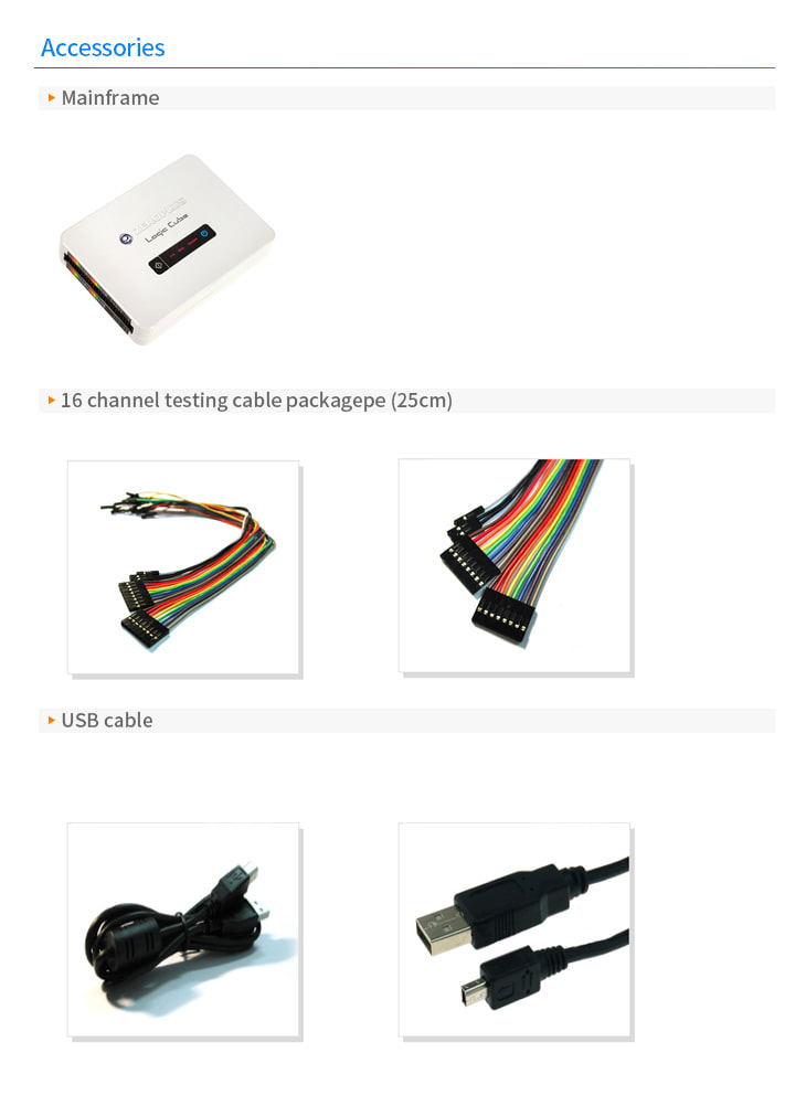
악세사리