PicoSource AS108
8 GHz Agile Synthesizer
휴대가능하고 가성비 좋은 전문가용 Agile Synthesizer
PicoSource™ AS108 Agile Synthesizer는 벤치탑 및 통합 모듈 애플리케이션의 요구 사항을 모두 충족하는 신호를 생성합니다. 300kHz~8GHz의 넓은 주파수 범위, 빠른 정착 및 프로그래밍 가능한 위상, 주파수 및 진폭은 저렴한 비용, 작은 설치 공간 및 12~15V 전력 요구 사항이라는 추가 이점과 함께 다양한 응용 분야에 적합합니다.
다중 채널 데이터 수집(DAQ)
데이터 로거당 최대 16개의 입력 채널
데이터 로거당 최대 4개의 출력 채널
동시에 최대 20개의 데이터 로거 사용
최대 1MS/s 샘플링 속도
USB 연결 및 전원 공급
데이터 수집 소프트웨어 및 SDK 포함
확장 가능한 다중 채널 데이터 수집 시스템
PicoLog 1012에는 12개의 입력 채널과 10비트 해상도가 있습니다. 강력한 PicoLog 1216에는 16개의 채널과 12비트 해상도가 있습니다. 더 많은 채널을 사용하기 원하면 새로운 PicoLog 6 소프트웨어를 사용하여 최대 20개의 Pico 데이터 로거를 하나의 PC에 연결할 수 있으므로 잠재적인 320채널 PicoLog 1000 시리즈 데이터 수집 시스템을 제공하는 것과 같습니다.또한 USB TC- 08 열전대(Thermocouple ) 데이터 로거와 같은 다른 장치와 함께 PcoLog 1000 로거을 사용할 수 있습니다.
외부 터미널 보드
외부 터미널 보드에는 납땜 없이 센서 와이어를 데이터 로거에 부착할 수 있는 나사 단자가 있습니다.
터미널 보드는 로거의 입력 범위를 오프셋(offset)하고 확장하기 위해 저항을 맞출 수 있는 위치에 있습니다.
Fast and accurate
10비트 또는 12비트 해상도와 다중 샘플링 모드를 갖춘 PicoLog 1000 시리즈 로거는 데이터 로깅에 사용자의 니즈를 완벽하게 충족합니다.
PicoLog 1000 시리즈에는 3가지 샘플링 모드
스트리밍 모드 : 채널 전압 판독값을 최대 100kS/s로 지속적으로 기록 가능
블록 모드 : 8000 샘플 버퍼로 제한된 duration동안 최고 1 MS/s logger 샘플 속도로 캡쳐함. 이러한 속도는 single-channel일 때 적용됨
실시간 continuous 샘플 모드: 어떠한 채널 갯수에서도 최대 1 kS/s의 속도로 자동측정됨. 일반적인 time-accurate reading을 제공됨
PicoLog 1000 PicoLog 6 software
PicoLog 6 data logging software for PicoLog 1000
PicoLog 6은 PicoLog 1000 전압 입력 데이터 로거를 위한 완전한 데이터 수집 소프트웨어 패키지입니다.
시각적이고 사용하기 쉬운 인터페이스를 제공하여 간단한 데이터부터 복잡한 수집을 신속하게 설정하고 데이터를 기록, 보기 및 분석할 수 있습니다.
실시간 데이터 수집 및 표시
간편한 구성 및 보기를 위한 비주얼 로거 및 채널 설정
Windows 7, 8 및 10(32 및 64비트), macOS, Linux 및 Raspberry Pi용 Raspbian에서 사용 가능
PC에 거의 무제한의 로깅 용량
강력한 데이터베이스 형식으로 데이터 손실 및 손상 최소화
간단하고 복잡한 프로그래밍 가능 알람
최대 4개의 독립적인 그래프 축
Lookup table 또는 방정식을 사용하여 채널을 확장 가능
데이터는 CSV, 클립보드 이미지 및 PDF로 내보내기 가능
동일한 PC에서 다양한 PicoLog 데이터 로거 및 PicoScope 오실로스코프 지원
아래의 table에서 PICOSCOPE® 2000 SERIES 의 모델을 확인하세요.
PicoSource AS108 Specifications
| General |
| Standard conditions are ambient temperature between 15°C and 30°C, 20 minutes after power-up. |
| Carrier wave |
| Parameter |
Applicable range and values |
Condition |
| Frequency range |
300 kHz to 8.192 GHz |
| Frequency resolution |
| 300 kHz to 125 MHz |
1 Hz |
| > 125 MHz to 4 GHz |
10 Hz |
| > 4 GHz |
20 Hz |
|
|
| Frequency settling time |
| 55 μs maximum |
50 μs typical |
|
|
to ±10 ppm |
| Frequency accuracy (internal reference) |
±5 ppm |
|
| Output power range |
−15 dBm to +15 dBm |
|
| Output power resolution |
0.1 dBm |
|
| Output power setting accuracy |
±1.5 dB |
|
| Output match (VSWR) |
| 1.8:1 maximum |
1.4:1 typical |
|
|
| Output amplitude settling time |
| to ±1 dB |
25 μs maximum |
| to ±0.1 dB |
200 μs maximum |
|
|
| Output protection |
25 V DC pk and 20 dBm |
|
| Phase noise at 10 kHz offset |
| 1 GHz |
−98 dBc/Hz maximum |
−100 dBc/Hz typical |
| 2 GHz |
−94 dBc/Hz maximum |
−96 dBc/Hz typical |
| 4 GHz |
−88 dBc/Hz maximum |
−90 dBc/Hz typical |
| 8 GHz |
−83 dBc/Hz maximum |
−85 dBc/Hz typical |
|
|
| |
 |
Measured phase noise at 1 GHz |
| Harmonics |
| −20 dBc maximum |
−26 dBc typical |
|
Output power set to +10 dBm |
| Sub-harmonics |
| −40 dBc maximum |
−46 dBc typical |
|
Output power set to +10 dBm |
| Spurious |
| −50 dBc maximum |
−60 dBc typical |
|
Output power set to +10 dBm |
| Sweep, hop and list modes |
| Parameter |
Applicable range and values |
Condition |
| Sweep, hop or list parameters |
Frequency; level; phase; frequency and level; phase and level |
|
| Discrete sweep or list points |
2 to 10 001 (or 2 to 1750 points when saving power-up settings to device) |
Hop is a special case of sweep with only two points. |
| Frequency stepping dwell time |
27 to 65 500 µs (or 27 µs to 1750 µs when saving power-up settings to device) |
Excepting any step exceeding ±2.2 GHz to or from the frequency band 7.0 GHz to 8.0 GHz, minimum dwell 100 µs. |
| Modulation |
| Parameter |
Applicable range and values |
Condition |
| Frequency range internal sine source |
10 Hz to 5 kHz |
|
| Internal modulation sample rate |
37 kS/s |
Sampled sideband spurs are generated at 37 kHz offset. At 1 kHz modulation typically < -30 dB relative to sidebands. |
| Frequency resolution and accuracy |
1 Hz resolution ± 0.1% accuracy |
|
| AM depth range |
| For carrier at 0 dBm |
5% minimum |
90% maximum |
| 0 dBm to 9 dBm |
5% minimum |
50% maximum |
|
|
| FM deviation |
2% carrier frequency or 200 kHz maximum |
|
| PM deviation |
±180° |
|
| External modulation input bandwidth |
DC coupled to 10 kHz |
|
| External modulation input sampling |
AM: 125 kS/s
FM/PM: 89 kS/s at 12-bit resolution |
Sampled sideband spurs are generated at 125 / 89 kHz offset. At 1 kHz modulation typically < -50 dB relative to sidebands. |
| External modulation input sensitivity |
| BNC(f) 600 Ω |
±1 V pk typical |
|
for selected depth or deviation |
| External modulation input protection |
±5 V DC + AC pk |
|
| Synchronization I/O |
| |
|
|
| Internal 10 MHz reference output |
| BNC(f) 50 Ω |
−3 dBm minimum |
0 dBm typical |
|
Into 50 Ω |
| External reference input |
| BNC(f) 50 Ω |
−6 dBm sensitivity |
6 dBm maximum |
|
|
| External reference lock range |
|
|
| Trigger input threshold voltage |
| BNC(f) 1 kΩ |
0.5 V minimum |
2.6 V maximum |
|
|
| Trigger output logic levels |
| BNC(f) |
Low 0.5 V maximum |
High 3.6 V minimum |
| Low 0.2 V maximum |
High 1.2 V minimum |
|
Into 1 kΩ
Into 50 Ω |
| Trigger output rise and fall times |
|
Into 50 Ω |
| Trigger in to trigger out delay |
|
Gives a lead of 17.5 µs to frequency / phase step, 37.5 µs to a level step. |
| Trigger out to triggered event delay |
17.5 µs typical |
Frequency or phase step |
| 37.5 µs typical |
Level step |
| Dwell period holds off (prevents receipt of) a further trigger. |
|
| Trigger input protection |
±10 V DC + AC peak |
|
| Trigger output protection |
±4 V DC + AC peak |
|
| Reference I/O protection |
4 V AC p-p ±15 V DC |
|
| Miscellaneous and environmental specifications |
| |
|
|
| Power requirements |
+12 V to +15 V DC, 12 W, 2.1 mm jack, centre pin positive |
|
| Control interface |
USB 2.0 |
|
| Dimensions |
W 173 mm x L 232 mm x H 56 mm |
Excluding connectors |
| Weight |
1.78 kg |
|
| Operating environment |
+5°C to +40°C, 80% RH non-condensing, Pollution Degree 2 |
|
| Storage environment |
−20°C to +50°C, 80% RH non-condensing, Pollution Degree 2 |
|
| Vibration tolerance |
0.5 g |
5 Hz to 300 Hz |
| Safety |
Declared conforming to:
EN61010-1:2010 and EN61010-2-030:2010
Safety requirements for electrical equipment for measurement, control and laboratory use, general requirements and for testing and measuring circuits. |
| EMC |
Declared conforming to:
EN61326-1:2013 Electrical equipment for measurement, control and laboratory use – EMC requirements. Group 1, Class B. (Emissions) EN61326-1:2013 Electrical equipment for measurement, control and laboratory use – EMC requirements. Basic Environment. (Immunity) EN61326-2-1:2013 Part 2-1: Test configurations, operational conditions and performance criteria for sensitive test and measurement equipment for unprotected applications.
CFR 47 Code of Federal Regulations FCC: part 15 Subpart B – Frequency devices – unintentional radiators. Radiated emissions standard. Class A. |
| ECCN coding |
EAR99 |
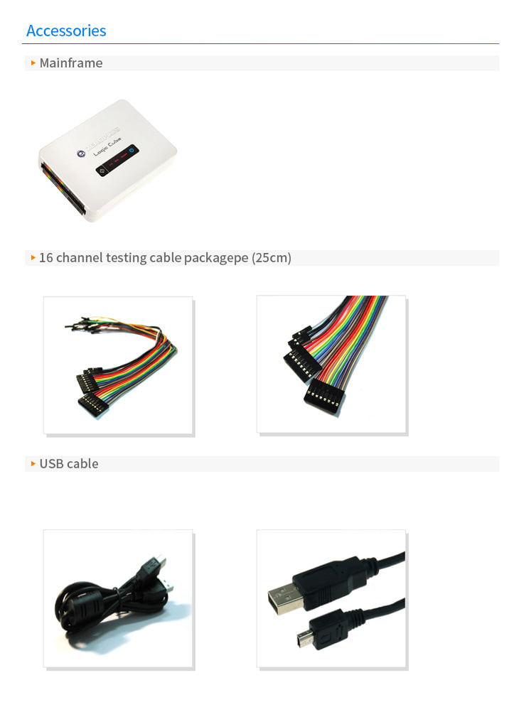
악세사리